BESC-G2 is second generation controller. It was designed to be used in lightweight vehicles such as ebikes, scooters and mopeds. Pair it with a powerful motor and battery supplying enough juice and it is perfect for your next crazy DIY project.
Unlike first generation BESC-G2 is highly optimised for cost/performance ratio. Connections are also optimised which makes connecting external equipment like throttles or bluetooth modules as easy as ever. A 12V power supply is also embedded to power LED light, phone chargers or any other equipment.

The board is relatively easy to solder with smallest components being 0603 and only one leadless package. Some basic electronics knowledge is required and intermediate soldering skills. A reflow oven is useful but not necessarily required. first things first, lets start with ordering PCBs.
Ordering PCBs
PCBs are standard FR4 4 layer boards. You have to get them in standard thickness of 1.6mm (2.0mm is even batter). Copper weight of 1 oz. is sufficient on internal and external layers. High current handling capacity of traces is enhanced with copper bus bars (solid copper wire) and solder. There are many of PCB manufaturers to choose from with some Chinese including Allpcb, PCBway and Bestpcb. Start by uploading gerber files to your favourite. Find a “Instant PCB quote” button and input next parameters.
- Size 231x67mm
- 1.6mm or 2mm PCB thickness,
- 1 oz. finished outer and inner copper ,
- min spacing 0.16mm or 6mils,
- min hole 0.3mm,
- soldermask and silk color as desired (black looks cool and green is standard),
- surface finish immersion gold (HASL is okay too if you’re on budget),
- tenting vias,
- flying probe test – yes,
- you can leave other parameters to their default.
10 PCBs should cost around 100€.
If you’re going to use reflow process for soldering don’t forget to order a stencil too. Upload gerbers to your favourite stencil manufacturer and let them put both sides (top and bottom paste layers) on a single stencil. Using a “framework” stencil is easier since it is already fixed in a frame.
Gerber files are available here. Click on icon to download latest (V1.1) gerber files.
Since enormous amount of work went into making this open source BLDC controller consider donating.
Ordering components
Most if not all components are available on Mouser. Other good suppliers are also Farnell and for folks outside of EU also Digikey and Arrow. Use the BOM file to order the components. Most suppliers have automated BOM (like Mouser’s BOM TOOL) processing so ordering should be easy.
https://eu.mouser.com/bomtool/
Flashing firmware
Click on icon below to download latest compiled firmware for BESC-G2. Firmware was last updated on 1. feb. 2021.
Since enormous amount of work went into making this open source BLDC controller consider donating.
Source code can be found on my Github repository.
To flash the firmware for the first time you’ll need to get ST-LINK programmer or a STM32 Nucleo board with integrated ST-LINK. You also need to download ST-LINK Utility.
Power up your BESC by connecting it to lab power supply or battery and short ignition jumper (J15 on PCB). 3V3 LED should light up. Connect SWD connector (J8 on PCB) to your programmer. See picture below for correct pinout of SWD.

Start up ST-LINK Utility and choose Target->Connect from dropdown menu. If you don’t get an error your MCU is working properly. Now choose Target->Program & Verify from the same menu or use CTRL+P shortcut. Browse for the file you just downloaded and click Program & Verify. Firmware is now flashed. Disconnect programmer. You should see ERR or THR LEDs light up. If not, power cycle your BESC.
Find and connect a micro USB cable and start VESC Tool®. Click connect and choose “Firmware” from the menu on left side. Click on “Bootloader” tab and flash the bootloader. From now on you can update firmware using VESC Tool®. Failure to do so will result in new firmware not storing on MCU when flashing from VESC Tool®.
HW bugs
There are two bugs in first version of hardware. If you ordered V1.1 you don’t have to fix these bugs.
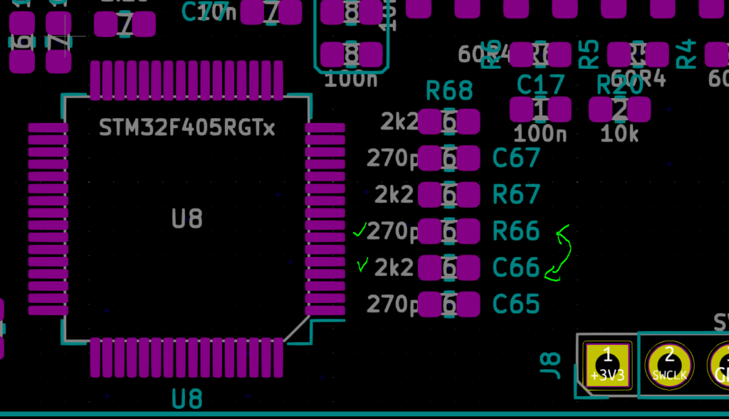
If you get sensor offset too high error you most likely switched R66 and C66. since their component designators are switched. Solder correct value components as shown on left side.
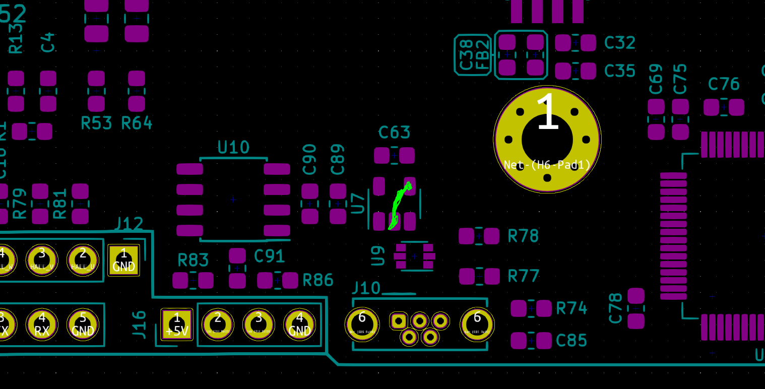
Gate enable signal doesn’t need logic inverter with new firmware. Remove U7 and bridge signal between pins 2 and 4 as shown on picture bellow.
Soldering busbars
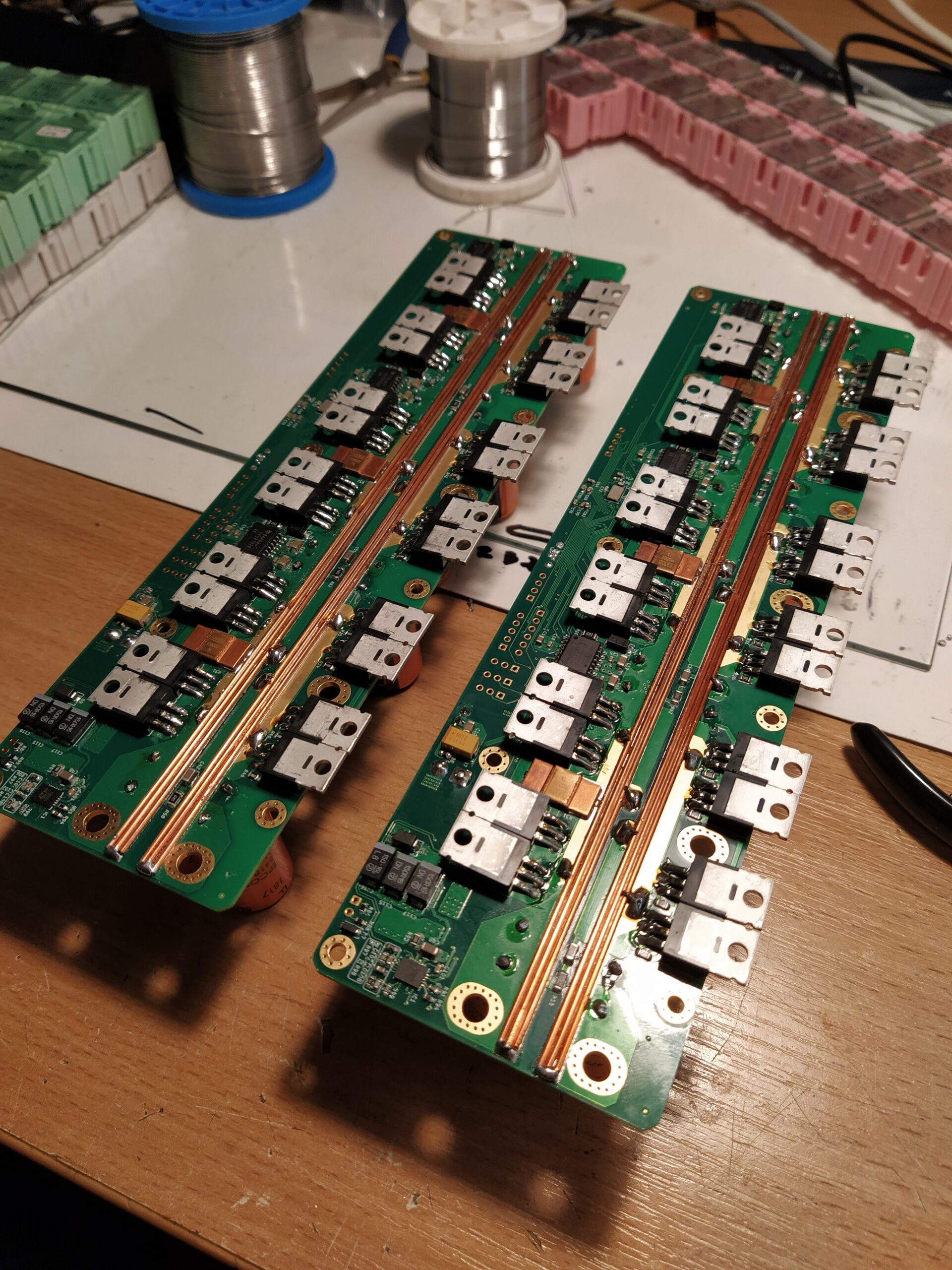
Busbars have an important role if you’re going to push this design to it’s max performance. While soldering a wire seems like an easy task some care should be taken to prevent circuit board bending.
Firstly you’ll have to straighten the solid wire as much as possible. I do it in the following way:
- Cut the wire a few centimetres longer than required to fit on the board. You’ll need 6 such wires.
- Put one side of the wire in a vice and grab the other side with pliers.
- Start pulling the wire with pliers. Once it stretches a bit it is fully straightened.
- Alternative way is to cut a 1m piece of wire then follow the same straightening process described above and finally cut wire to correct length.
Be careful not to bend wires when removing them from the vice.
Soldering is of busbar (wires) is best done using solder paste and reflow oven while also soldering other elements on board at the same time. The key is to heat the board as evenly as possible. Heating just one side of the board will produce significant board bending and may even de-laminate the board. Soldering wires using soldering iron is not recommended. Alternative for melting solder paste instead of reflow oven is hot air gun. Make sure you heat the board evenly by moving the hot air gun from one side of the board to another with slow motion.
Same soldering process also applies to top busbars. They may be omitted for lower current operation.
Do not forget to enhance current capacity of MOSFET terminals using solder.
Interfacing MOSFETs to a heatsink
Tabs of mosfets are electrically connected to either positive supply or motor phase. To prevent shorts an insulating material has to be placed between mosfet tabs and heatsink. Tabs of mosfets next to each other may touch. The material that’s electrically insulating mosfets has to have good thermal conductivity. Using 0.635mm thick ceramics insulator is recommended. You can get in on ebay. You will also need themal paste to grease the heatsink and mosfets. You have to offset the PCB just enough using M3 spacers that when board is screwed in place good contact is made between mosfet tabs, ceramic insulator and heatsink.
Before applying power to your motor for the first time
Before applying power to your motor for the first time you should firstly check if the BESC is soldered correctly and there are no errors in assembly.
It is recommended to connect your BESC to a lab power supply with 0.5A current limit for the first time. If 3V3 LED lights up and you successfully flashed the firmware it is time to connect BESC to your PC with USB cable.
Start VESC Tool®, connect to your BESC and click “Realtime data” from the menu on the left. To stream live data click on “Stream live data” button on the right. If there are no fault conditions you are good to go. If you get a fault head over to FAQ for instructions how to proceed.
Checking voltage sense
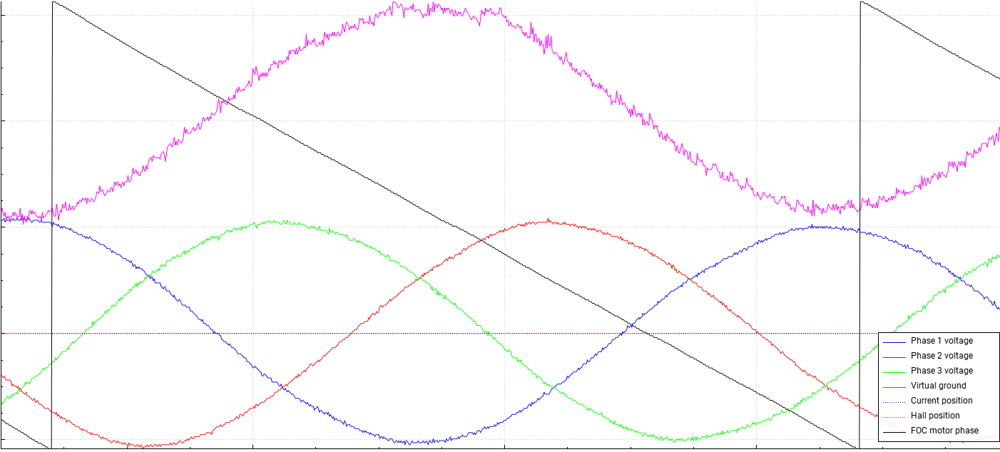
It is time to connect your motor to BESC. Be careful not to apply any power to it just yet. Head over to “Sampled Data” from the menu on the left. Select BEMF tab. Spin the motor with your hand and click “Sample now” button while the motor is still spinning. If everything is okay you should get three sine shaped voltages. Something like this:
Checking current sense
This will get a bit more exciting because for this step we will have to fire up the power stage. Before proceeding make sure your power supply current is limited to keep magic smoke in your transistors in case you soldered something wrong.
Click anchor icon to apply full brake to your motor. If you don’t get a fault half of the work is already done. Try to spin the motor by hand. You should feel constant resistance in any direction. If it is jerky there’s something wrong.
Click Current tab in “Sampled data” window and hit “Sample now” button while spinning the motor (slowly of course). Similarly to voltage you should see three sine shaped currents. After that you can be confident that your BESC is assembled correctly. Now you can proceed with detecting motor parameters as you would on any VESC® based motor controller.